In this
section, the entire IO board is soldered together and the USB is tested.
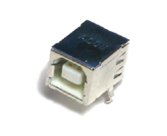
Be sure to follow the instructions for how to solder in the surface
mount USB chip.
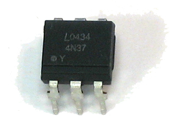
Note: in batch #6 we've started to notice that the optoisolators are possibly made to a different specification. If MIDI out and MIDI thru are working but MIDI in is not, try upping R16 to 120 or 150 ohms!
If you are concerned that you will not be able to solder the USB chip, we are offering, as an extra service, to prebuild & test USB. Just make sure you request it when you order your kit.
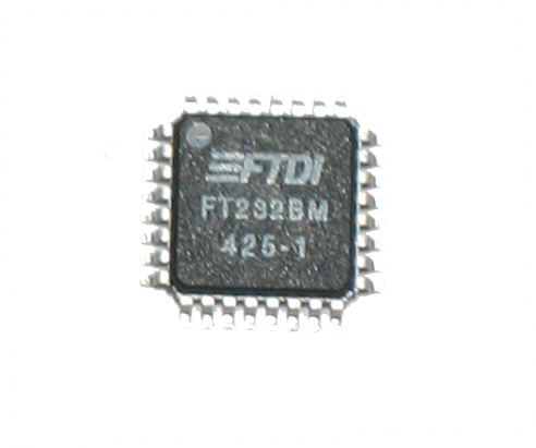
Since the USB chip is the most difficult part to
solder, this should be done first, so that there is plenty of space
to work in. There are a few techniques for soldering SMD parts.
The two techniques I am a fan of are:
- Soldering with silver solder as carefully as possible, and then
using solder wick to clean up
- Soldering with solder paste, and then using solder wick to clean
up.
There are a bunch of tutorial sites on this (just search on google!):
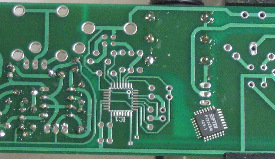
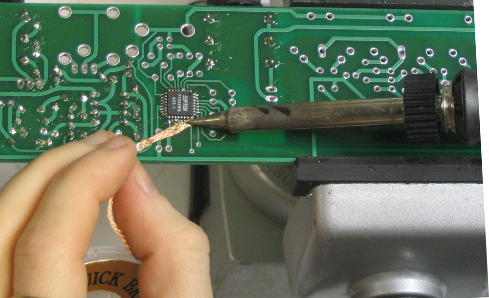
Here's a straightforward method for soldering this chip using
solder & wick. The magnifying glass comes in very very handy here! Its essential to check for bridged pins and unconnected pins.
- If you have flux, spread some on the pads, this will help bridging.
The solder mask should also help a lot.
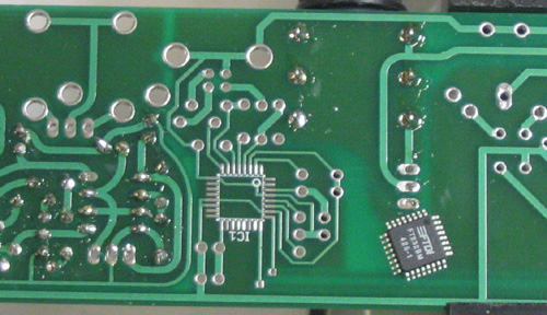
- Place a small amount of solder on a corner pad.
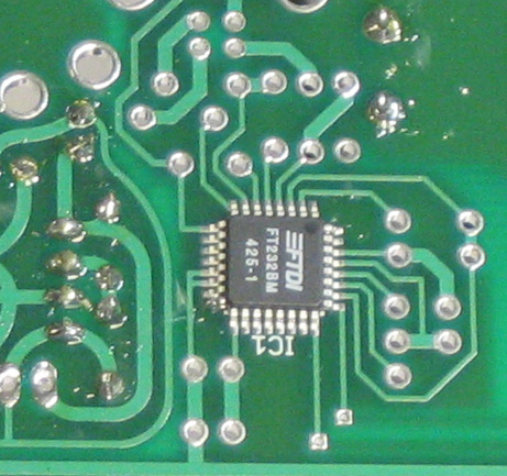
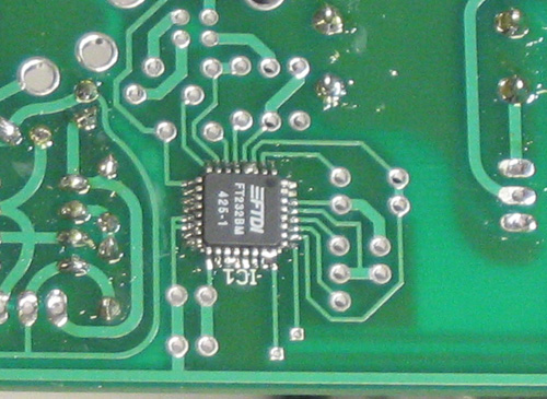
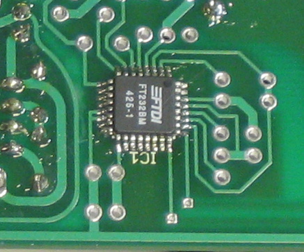
- Using tweezers, position the chip correctly (the circle on the
picture matches the circle indent on the chip) and heat the corner
pad. When the soldered pad is heated up, align the chip in the
right location, then pull the soldering iron away.
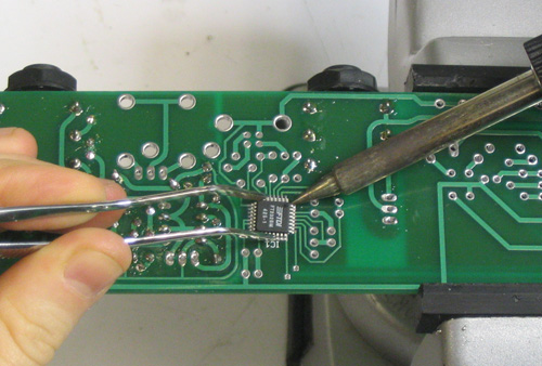
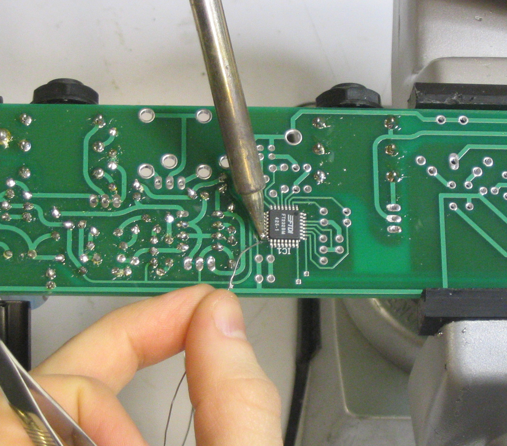
- Place a small amount of solder on the iron tip. Tack the opposite
corner, holding the chip steady with the tweezers.
- Double check that you have the chip positioned right.
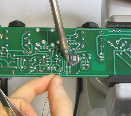
- As carefully as possible, solder the remaining pins. Heat where
the pin and pad meet, then quickly touch some solder to the pin,
the solder should flow down to the pad.
- Dont worry if you bridge some pins, just fix it with the wick.

- When you're done, look at the board under a magnifier, or hold
up to the light at an angle to see all the pins
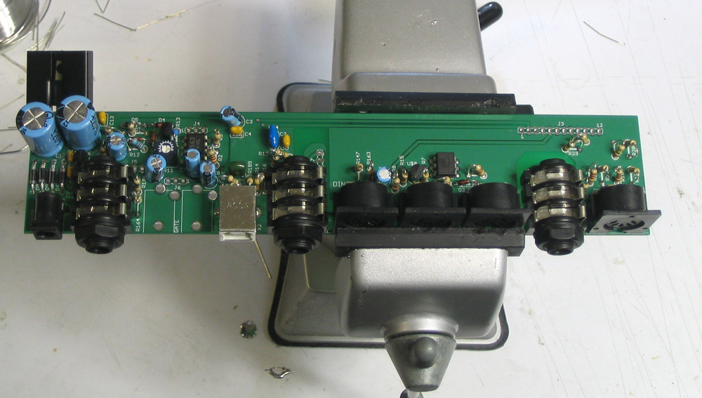
- Ok now that you're done with the USB chip and you're pretty
sure its soldered correctly, solder in all the rest of the components
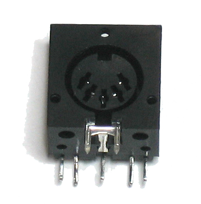
on the IO board. When soldering in the MIDI/DINSYNC connectors,
make sure to 'pre-stress' them as they are a little flimsy: press
them back so that the face is flush with the PCB while soldering
them in. Be sure to use lots of solder on all the connector components
to make a good mechanical bond.
- Power the IO board, but don't connect it to the main board
- Plug in the USB into a computer.
- The computer should detect a "Serial <-> USB"
chip and request a driver.
- Download the driver
from FTDI. Make sure to grab the VCP driver. Install it.
Verify that a new COM port is created (under Windows, look
under hardware control panel)