This is an old revision of the document!
Wiring
The PN532 chip and breakout is designed to be used by 3.3V systems. To use it with a 5V system such as an Arduino, a level shifter is required to convert the high voltages into 3.3V. If you have a 3.3V embedded system you won't have to use the shifter of course!
To begin, we'll solder in the header to the breakout board. You'll need two small 3-pin pieces of header and one 8-pin piece. You can break these off of a large piece
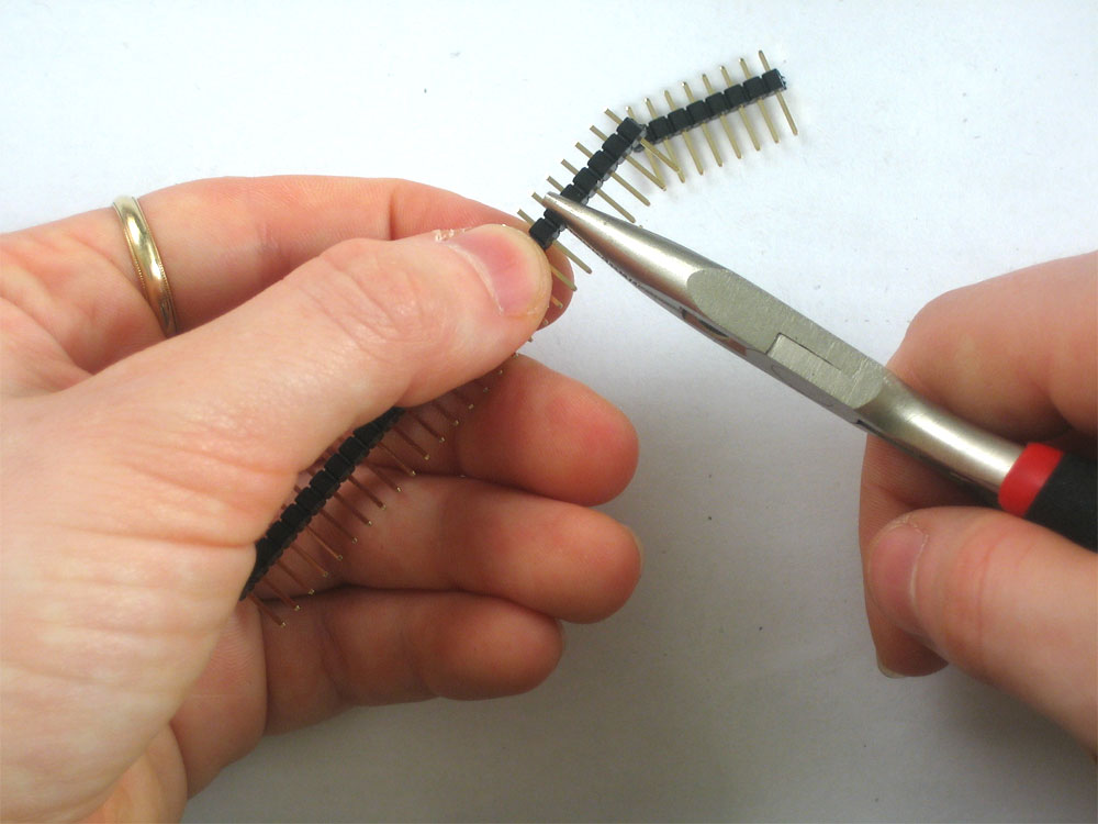


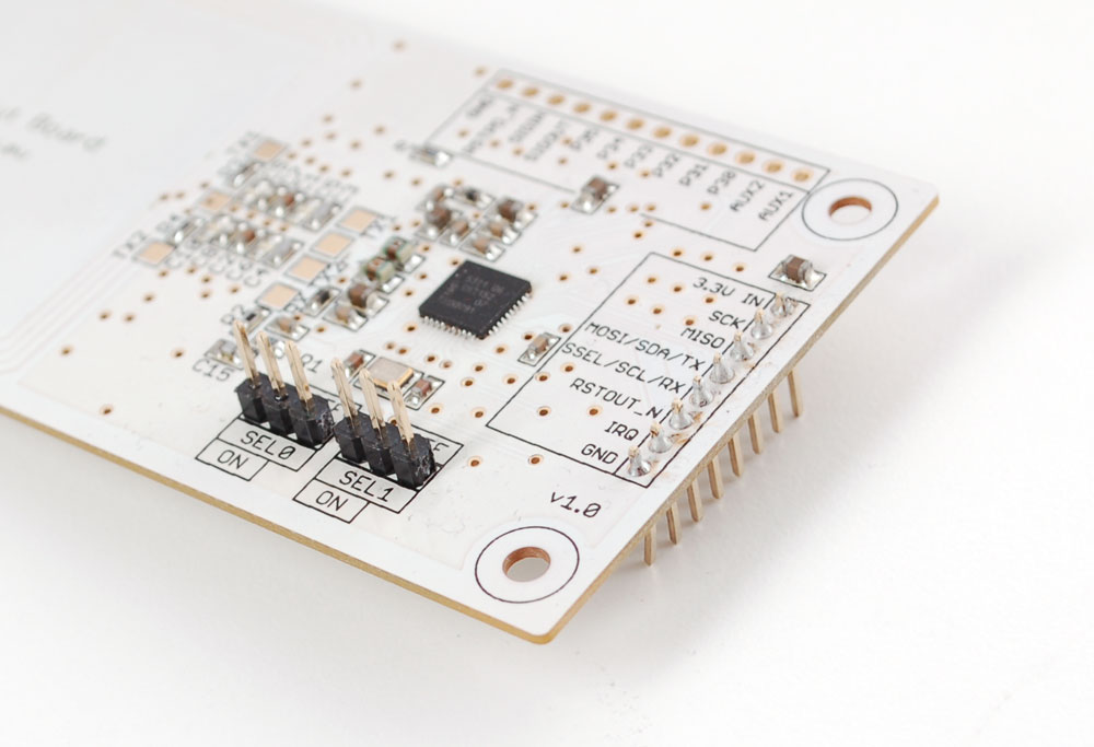
Solder the two small pieces to the SEL0 and SEL1 pads. These are interface selectors for the chip. Depending on how the jumpers are inserted the chip will talk in TTL serial, i2c or SPI. Also solder a strip to the end so you can plug it into a breadboard
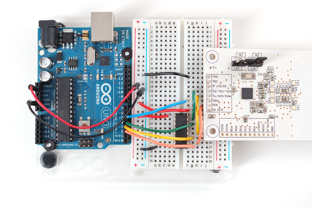
Wire up the 4050 level shifter chip to the Arduino as shown. The notch in the 4050 is at the 'top' in this image.
- Arduino digital pin 2 is connected to 4050 pin 9 (orange wire)
- Arduino digital pin 3 is connected to 4050 pin 11 (yellow wire)
- Arduino digital pin 4 is connected to 4050 pin 14 (green wire)
On the breakout board
- 3.3Vin is connected to the Arduino 3.3V pn
- SCK is connected to 4050 pin 10 (orange wire)
- MISO is connected to Arduino pin 5 (blue wire)
- MOSI is connected to 4050 pin 12 (yellow wire)
- SSEL is connected to 4050 pin 15 (green wire)
- GND connects to Arduino ground (black wire)
Also connect 4050 pin #1 to 3.3V and pin #7 to ground.
Click to see a larger image. The red power wire should be connected to the 3.3v pin on the Arduino!
Also, we need to select SPI as the interface so on SEL1 place the jumper in the ON position. for SEL0 place the jumper in the OFF position
That's it! Later on you can change what Arduino pins you are using but for the beginning test we suggest matching our wiring.
